Tuesday 12 June 2018

Personal Reflection


Assignment 3: Personal Reflection


After completing four unique and different shaped objects, the aluminium model I have chosen to critically review is the tray.The tray looked like a simple shaped object however when fabricating the element it was not as easy as it looked.Throughout the creation of the tray I had learnt a variety of things and was able to gain a greater knowledge on the aluminium forming process.


Strengths 

  1. After having completed two models previously some of the techniques used in creating the two objects before, were a significant benefit to forming the delicate shape in particularly the sides of the tray.
  2. In this project my smoothing/flattening out techniques were developed significantly in comparison to the bowl.The edges all had a nice rounded and smooth finish.

Weaknesses


  1. Due to being from a construction background, my ability to hit the aluminium softly was quite challenging, hence was a problem when trying to bend the sides of the tray up.Due to over hammering the side actually teared and was unfixable.
  2. As much as I made the shape perfect it was let down due to the fact it did not correspond with the other persons tray.Due to the split in the side it didn't provide the correct fit to my partners tray.
  3. Being able to get the perfect height of the sides all the way around due to stretching of the aluminium was also a let down for me.


Alternatives

  1. In creating the tray again, i will definetly take more time and patience in achieving the required curves and edges of the tray to make it look better.


Adequately, the skills i have learnt in other object making processes were useful specifically the use of moulds, flattening out, plemishing. However, at the same time skills that i learnt in the bowl when rounding the surface using a sandbag and timber stump were not useful. 


Overall, this was a quite enjoyable project, which further developed my aluminium making skills essentially providing me with a greater degree of skill and knowledge for when i created my petrol tank.


Tuesday 22 May 2018

Petrol Tank

Aluminium Fuel Tank ( The lid of the tank )

May 23rd, 2018


Aim: To create an Aluminium Fuel tank, in 3 parts providing a seamless connection once finished.My main objective was to create the lid of the tank


The petrol tank form is quite a challenging yet simple design which requires a certain standard of skill and aluminium moulding processes, in order to provide the abnormal shape and definition of the model.In order to replicate the petrol tank a large amount of skill and knowledge from our previous tutorials i.e( bowl making, tray making & the blister techniques) ,were used in order to give the exact shape and sophistication of the tank.

Firstly, before creating the lid of the tank the petrol tanks form must be created in order to be used as a reference point for all three parts that are to be moulded.The process followed in order to achieve this model was as follows.

Measure up the tank in order to provide realistic dimensions which will be used to be put into the modelling program to form the mould.Once these dimensions have been established, using the RHINO digital modelling program the stencils to form the petrol tank mould are then designed using this program, to provide an exact duplicate of the petrol tank.(A KEY IMPORTANT FACTOR WAS ENSURING THE CURVATURES RUNNING UP AND DOWN & LEFT AND RIGHT MATCHED THE MEASUREMENT AND RADIUSES OF THE TANK, TO PROVIDE A SEAMLESS ROUNDED EDGE.)

Once the Rhino Slicer model has been finalised and matches the design requirement of the mould, using a laser cutting machine and 3mm ply, the stencils created in the program are then precisely cut onto the board to form a jigsaw puzzle of the tank.


Using the stencil cutouts, the pieces are then joined together to form the irregular form of the petrol tank.In order to strengthen the mould and prevent it from collapsing when moulding the aluminium, using a hot glue gun all the seams and joints of the stencils were glued, essentially providing a rigid structure for the tank to be formed.


The mould was then split into three quadrants which will effectively provide the greatest look when joined together.The easiest way decided in order to provide greatest efficiency was to seperate the sides into two pieces then the lid on the top.


PROCESS

Being responsible for the tanks lid, the following process was implemented in order to achieve the required form and design:

Step 1

Using tracing paper, trace the shape of the lid on to the piece of paper to provide a stencil for the sizing of the lid.Once traced the paper stencil is to be cut out using scissors, leaving approximately 10mm on each side for shrinkage and any minor mistakes.


Step 2

When the paper stencil has been cut and it suits the shape of the lid, trace the stencil onto the annealed piece of aluminium using a marker, followed by a sharp metal point in order to engrave the line clearer.Then using a sheet metal cutter or aviation snips carefully cut out the stencil ensuring a even smooth cut all the way around.After cutting the shape run a file or sandpaper along the edges to remove the burrs or any uneven edges.


Step 3

In order to create the shape and curve of the mould, using the ply stencil trace the curve of the lid onto a piece of 18mm plywood.Once traced onto the plywood, cutout the shape using a band saw then using a drum sander smooth the edges.Duplicate this process several times and drill all the pieces together with screws, until the stencil is wide enough to fit the aluminium stencil. 


Step 4

Once the form has been made clamp it into a bench vice, and place the aluminium stencil on top.Then using a fibre glass hammer using strategic hits, hammer the aluminium into the mould until you receive the shape desired.During this process it is important that the stencil is securely held down to prevent the shape being irregular and not being able to match the mould.


Step 5

Then, due to the top half of the tank having a reversed bowl pro-form, using a marker mark the centre of the top top half piece of the tank  and draw circles around the centre to be used as guidelines for moulding it into the bowl shape.Then using a sand bag and a fibre glass mallet begin to hammer the aluminium from the centre out , slowly moulding it and curving the edges to form the round outer-skin of the tank.


Step 6

After, the bulk of the shape has been formed with the sand bag, then using a depressed tree stump and rounded fibreglass mallet, hammer the form into the mould at the correct angle for the full 360 degrees of the piece.By doing this it will essentially define the edges and curve of the top half of the tank to provide a greater seamless finish when joining it with the side pieces.It is also very important to continue matching the piece your moulding over the reference mould in order to prevent it from being incorrect.


Step 7

Once the top half shape has been formed, then using the same process as the rounded top half, however with more gentle curves, using a sand bag and depressed tree stump hammer the body of the lid to form the curve that essentially defines the length part of the tank.This is a repetitive process which requires strategic hammering, and continuous matching to the already made mould, to prevent distortion.It is important to ensure that during this process that you do not over hammer the aluminium as it will crack or bend and wont be fixable especially due to how delicate the curvature of the lid is.


Step 8

Then, after the shape of the aluminium suits the mould, it is then time to smooth out the lid.Using a english wheel gently wheel out the formed piece of aluminium removing the depressions formed by the mallet as well as providing smoother rounder edges for the lid.Again during this process it is important to continuously check the mould with the aluminium lid to prevent it from distorting as a result of the english wheel.Then, using a dolly and mallet smooth out the imperfections that couldn't be done with the english wheel.Essentially, properly done this will provide a professional tank finish with a seamless finish.


Step 9

Lastly, once completed joint the pieces together and using aviation snips cut out any imperfections or overhanging pieces of metal from the aluminium lid in order to allow the pieces to fit together perfectly.Once done the tank is complete.


Tuesday 3 April 2018

Blister

Aluminium Blister

April 4th, 2018


Aim: To create an Aluminium Blister using techniques shown to us in class

Objectives: 
  1. Smooth even finish
  2. Evenly rounded blister which is clearly defined in the aluminium
  3. Blister free from cracks and dents
  4. Stand out from the rest


 Process:


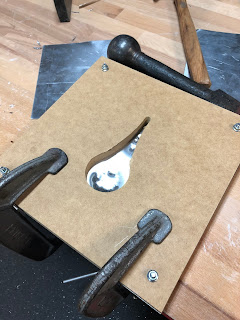
Firstly, in order to create the shape of the blister the first thing that was required to be done was create a mould in which the blister will be formed.Using a CNC machine which had a pre-made impregnated design the machine cut out two identical raindrop looking shapes into a piece of 15mm MDF.Once they were cut I was then required to remove excess material using a router as well as some sandpaper to achieve identical shapes when joining the two pieces of MDF together.


Secondly, once my moulds were completed I was then required to cut the piece of aluminium using a guillotine, to be used to in conjunction with the MDF to from the blister.Once cut I marked the centre of the sheet and sandwiched the sheet between the two pieces of MDF ensuring the centre I had marked out lined up with the centre of the mould.I then used 4 bolts and bolted the two pieces together through the pre- drilled holes from the CNC cutout.After I had ensured they were tightened up I then used 2 G clamps and clamped the mould onto two pieces of 16mm ply on the bench which were used to elevate the mould to provide the blister depth required.


Thirdly, utilising a fibreglass/plastic mallet I began to slowly tap the inside of the mould to begin depressing the aluminium into the rounded blister shape.This process was very frustrating and delicate as tapping too hard will cause large dents in the aluminium as well as potentially causing it to tear.Hence, in order to achieve a nice and professional finish I was required to softly and delicately tap the aluminium in a repetitive process to I achieved the required depression of the material I needed.


Due to the extent of the shape and the fine detail of the blister the mallet was unable to be used to provide greater depth into the blister, especially in the narrow parts as the mallets head was to big for the gap.Hence in order to achieve this detail for these areas, I was required to form a jig using a piece of timber and a drum sander to allow me to mould the aluminium edges to a perfect blister.This was very complicated as the timber couldn't be too flat otherwise it would've caused dents hence the reason why I had to round the edges perfectly to achieve an even curve throughout the whole blister. Using the jig and a mallet i was able to gain greater definition on the edges with more defined curves and depth, which ultimately provided a flatter and more even depression to the mould.


After hours of hammering and moulding I then removed the aluminium from the MDF mould.Using a guillotine I cut the aluminium to equal size TO allow the blister to stand out more.After that i gave it a sand & buff with some steel wool and the final product as seen above was complete :)


Tuesday 27 March 2018

Tray

Aluminium Tray

March 28th, 2018


Aim: To create an Aluminium Tray using techniques shown to us in class

Objectives: 
  1. Smooth even finish
  2. Minimal Burs and an even smooth edge
  3. Must create an tray identical to designated group member
  4. Mustn't have gaps in between the to trays when aligned and the base must be flat not rounded
  5. Stand out from the rest


 Process:


The first thing in creating the aluminium tray was to create a mould in which the tray will be formed on.Using a CNC machine a template which was already created in the system was cut out of a thin piece of PLY to provide the final shape of the tray.Using this template the design was traced onto pre-cut plywood and cut out and shaped using a disc sander.Once i achieved the correct curves i then traced the mould onto the piece of aluminium, leaving ample room to achieve a 10mm height on the tray


Once i had traced the mould I then cut out the trays shape using aviation snips.Then using the two moulds i sandwiched the aluminium between the them ensuring they are even on both sides and then placed it into the vice clamp.Using a plastic mallet I began to slowly and carefully form the aluminium to suit the mould of the tray.This process followed around the whole tray until i achieved the required tray look i needed.
The hammering process was very challenging due to the fact that each hit was required to be pin pointed and not hit to hard otherwise it would have ruined the shape.Hence, in order to achieve a greater look it took me longer then expected.


Then after I was happy with the shape of the tray i began to smooth out the edges, curves and base of the tray to provide a nice smooth and neat finish.After sanding, planishing and hours of tedious work i finally finished and produce the below tray masterpiece.


Our tray didn't match 100% probably only 95 % but it was pretty good for our first time considering we had never done that kind of stuff before